Color Models#
The purpose of a color model is to facilitate the specification of colors in some standard generally accepted way. In essence, a color model is a specification of a 3D coordinate system and a subspace within that system where each color is represented by a single point.
Each industry that uses color employs the most suitable color model. For example, the RGB color model is used in computer graphics, YUV or YCbCr are used in video systems, PhotoYCC* is used in Photo CD* production. Transferring color information from one industry to another requires transformation from one set of values to another. oneIPL provides a wide number of functions to convert different color spaces to RGB and vice versa.
RGB Color Model
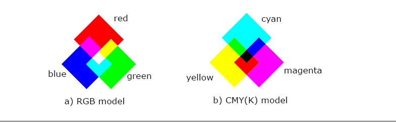
In the RGB model, each color appears as a combination of red, green, and blue. This model is called additive, and the colors are called primary colors. The primary colors can be added to produce the secondary colors of light (see Figure “Primary and Secondary Colors for RGB and CMYK Models”) - magenta (red plus blue), cyan (green plus blue), and yellow (red plus green). The combination of red, green, and blue at full intensities makes white.
Primary and Secondary Colors for RGB and CMYK Models
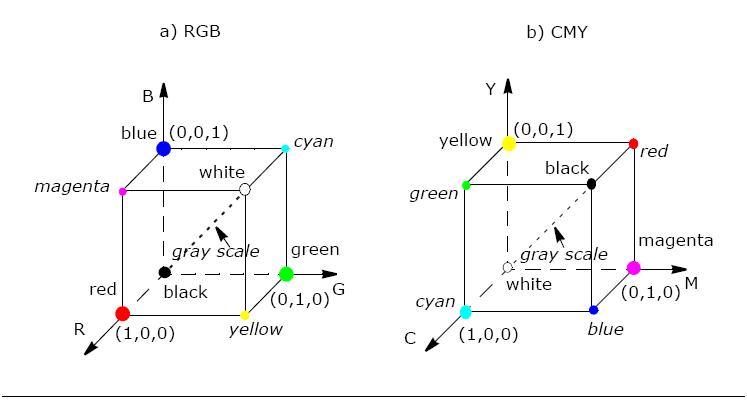
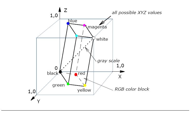
The color subspace of interest is a cube shown in Figure “RGB and CMY Color Models” (RGB values are normalized to 0..1), in which RGB values are at three corners; cyan, magenta, and yellow are the three other corners, black is at their origin; and white is at the corner farthest from the origin.
The gray scale extends from black to white along the diagonal joining these two points. The colors are the points on or inside the cube, defined by vectors extending from the origin.
Thus, images in the RGB color model consist of three independent image planes, one for each primary color.
As a rule, the oneIPL color conversion functions operate with non-linear gamma-corrected images R’G’B’.
The importance of the RGB color model is that it relates very closely to the way that the human eye perceives color. RGB is a basic color model for computer graphics because color displays use red, green, and blue to create the desired color. Therefore, the choice of the RGB color space simplifies the architecture and design of the system. Besides, a system that is designed using the RGB color space can take advantage of a large number of existing software routines, because this color space has been around for a number of years.
RGB and CMY Color Models
However, RGB is not very efficient when dealing with real-world images. To generate any color within the RGB color cube, all three RGB components need to be of equal pixel depth and display resolution. Also, any modification of the image requires modification of all three planes.
CMYK Color Model
The CMYK color model is a subset of the RGB model and is primarily used in color print production. CMYK is an acronym for cyan, magenta, and yellow along with black (noted as K). The CMYK color space is subtractive, meaning that cyan, magenta yellow, and black pigments or inks are applied to a white surface to subtract some color from white surface to create the final color. For example (see Figure “Primary and Secondary Colors for RGB and CMYK Models”), cyan is white minus red, magenta is white minus green, and yellow is white minus blue. Subtracting all colors by combining the CMY at full saturation should, in theory, render black. However, impurities in the existing CMY inks make full and equal saturation impossible, and some RGB light does filter through, rendering a muddy brown color. Therefore, the black ink is added to CMY. The CMY cube is shown in Figure “RGB and CMY Color Models”, in which CMY values are at three corners; red, green, and blue are the three other corners, white is at the origin; and black is at the corner farthest from the origin.
YUV Color Model
The YUV color model is the basic color model used in analogue color TV broadcasting. Initially YUV is the re-coding of RGB for transmission efficiency (minimizing bandwidth) and for downward compatibility with black-and white television. The YUV color space is “derived” from the RGB space. It comprises the luminance (Y) and two color difference (U, V) components. The luminance can be computed as a weighted sum of red, green and blue components; the color difference, or chrominance, components are formed by subtracting luminance from blue and from red.
The principal advantage of the YUV model in image processing is decoupling of luminance and color information. The importance of this decoupling is that the luminance component of an image can be processed without affecting its color component. For example, the histogram equalization of the color image in the YUV format may be performed simply by applying histogram equalization to its Y component.
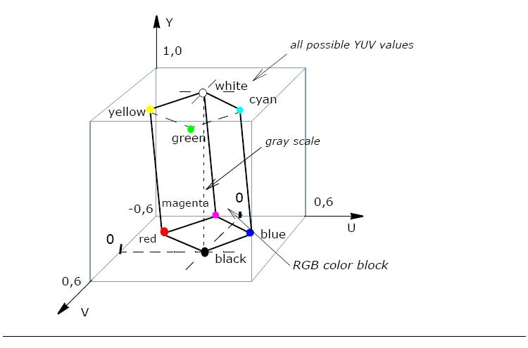
There are many combinations of YUV values from nominal ranges that result in invalid RGB values, because the possible RGB colors occupy only part of the YUV space limited by these ranges. Figure “RGB Colors Cube in the YUV Color Space” shows the valid color block in the YUV space that corresponds to the RGB color cube RGB values that are normalized to [0..1]).
The Y’U’V’ notation means that the components are derived from gamma-corrected R’G’B’. Weighted sum of these non-linear components forms a signal representative of luminance that is called lumaY’. (Luma is often loosely referred to as luminance, so you need to be careful to determine whether a particular author assigns a linear or non-linear interpretation to the term luminance).
The oneIPL functions use the following basic equation ([Jack01]) to convert between gamma-corrected R’G’B’ and Y’U’V’ models:
Y'= 0.299*R' + 0.587*G' + 0.114*B'
U'= -0.147*R' - 0.289*G' + 0.436*B' = 0.492*(B'- Y')
V'= 0.615*R' - 0.515*G' - 0.100*B' = 0.877*(R'- Y')
R' = Y' + 1.140*V'
G' = Y' - 0.394*U' - 0.581*V'
B' = Y' + 2.032*U'
There are several YUV sampling formats such as 4:4:4, 4:2:2, and 4:2:0 that are supported by the oneIPL color conversion functions and are described later in this chapter in Image Downsampling.
YCbCr and YCCK Color Models
The YCbCr color space is used for component digital video and was developed as part of the ITU-R BT.601 Recommendation. YCbCr is a scaled and offset version of the YUV color space.
The oneIPL functions use the following basic equations [Jack01] to convert between R’G’B’ in the range 0-255 and Y’Cb’Cr’ (this notation means that all components are derived from gamma-corrected R’G’B’):
Y' = 0.257*R' + 0.504*G' + 0.098*B' + 16
Cb' = -0.148*R' - 0.291*G' + 0.439*B' + 128
Cr' = 0.439*R' - 0.368*G' - 0.071*B' + 128
R' = 1.164*(Y'-16) + 1.596*(Cr'-128)
G' = 1.164*(Y'-16) - 0.813*(Cr'-128) - 0.392*(Cb'-128)
B' = 1.164*(Y'-16) + 2.017*(Cb'-128)
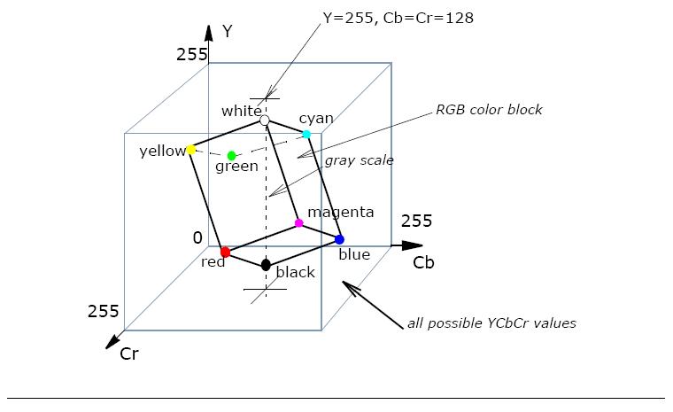
Possible RGB colors occupy only part of the YCbCr color space (see Figure “RGB Colors Cube in the YCbCr Space”) limited by the nominal ranges, therefore there are many YCbCr combinations that result in invalid RGB values.
There are several YCbCr sampling layouts such as 4:4:4, 4:2:2, 4:1:1, and 4:2:0, which are supported by the oneIPL color conversion functions and are described later in this chapter in Image Downsampling.
PhotoYCC Color Model
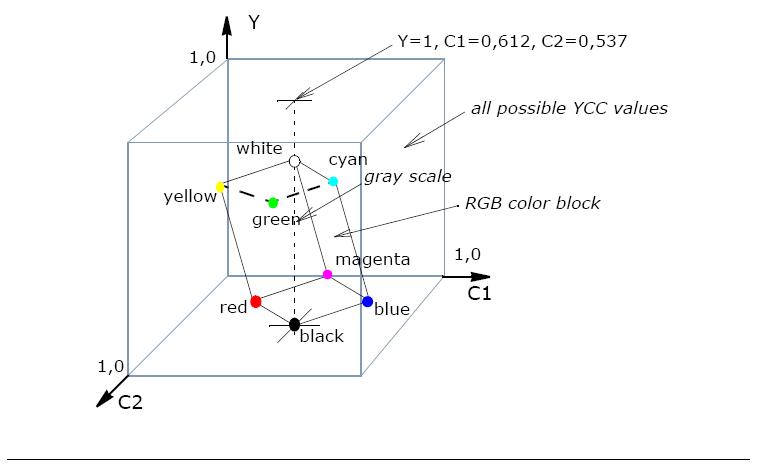
The Kodak* PhotoYCC* was developed for encoding Photo CD* image data. It is based on both the ITU Recommendations 601 and 709, using luminance-chrominance representation of color like in BT.601 YCbCr and BT.709 ([ITU709]). This model comprises luminance (Y) and two color difference, or chrominance (C1, C2) components. The PhotoYCC is optimized for the color photographic material, and provides a color gamut that is greater than the one that can currently be displayed.
The oneIPL functions use the following basic equations [Jack01] to convert non-linear gamma-corrected R’G’B’ to Y’C’C’:
Y' = 0.213*R' + 0.419*G' + 0.081*B'
C1' = -0.131*R' - 0.256*G' + 0.387*B'+ 0.612
C2' = 0.373*R' - 0.312*R' - 0.061*B' + 0.537
The equations above are given on the assumption that R’,G’, and B’ values are normalized to the range [0..1].
Since the PhotoYCC model attempts to preserve the dynamic range of film, decoding PhotoYCC images requires selection of a color space and range appropriate for the output device. Thus, the decoding equations are not always the exact inverse of the encoding equations. The following equations [Jack01] are used in oneIPL to generate R’G’B’ values for driving a CRT display and require a unity relationship between the luma in the encoded image and the displayed image:
R' = 0.981 * Y + 1.315 * (C2 - 0.537)
G' = 0.981 * Y - 0.311 * (C1 - 0.612)- 0.669 * (C2 - 0.537)
B' = 0.981 * Y + 1.601 * (C1 - 0.612)
The equations above are given on the assumption that source Y, C1 and C2 values are normalized to the range [0..1], and the display primaries have the chromaticity values in accordance with [ITU709] specifications.
The possible RGB colors occupy only part of the YCC color space (see Figure “RGB Colors in the YCC Color Space”) limited by the nominal ranges, therefore there are many YCC combinations that result in invalid RGB values.
YCoCg Color Models
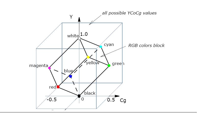
The YCoCg color model was developed to increase the effectiveness of the image compression [Malvar03]. This color model comprises the luminance (Y) and two color difference components (Co - offset orange, Cg - offset green).
The oneIPL functions use the following simple basic equations [Malvar03] to convert between RGB and YCoCg:
Y = R/4 + G/2 + B/4
The YCoCg color model was developed to increase the effectiveness of the image compression [Malvar03]. This color model comprises the luminance (Y) and two color difference components (Co - offset orange, Cg - offset green).
Co = R/2 - B/2
The oneIPL functions use the following simple basic equations [Malvar03] to convert between RGB and YCoCg:
Cg = -R/4 + G/2 - B/4
R = Y + Co - Cg
G = Y + Cg
B = Y - Co - Cg
A variation of this color space which is called YCoCg-R, enables transformation reversibility with a smaller dynamic range requirements than does YCoCg [Malvar03-1].
The possible RGB colors occupy only part of the YCoCg color space (see Figure “RGB Color Cube in the YCoCg Color Space”) limited by the nominal ranges, therfore there are many YCoCg combinations that result in invalid RGB values.
HSV, and HLS Color Models
The HLS (hue, lightness, saturation) and HSV (hue, saturation, value) color models were developed to be more “intuitive” in manipulating with color and were designed to approximate the way humans perceive and interpret color.
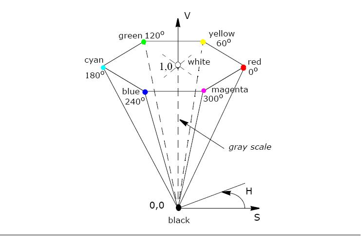
Hue defines the color itself. The values for the hue axis vary from 0 to 360 beginning and ending with red and running through green, blue and all intermediary colors.
Saturation indicates the degree to which the hue differs from a neutral gray. The values run from 0, which means no color saturation, to 1, which is the fullest saturation of a given hue at a given illumination.
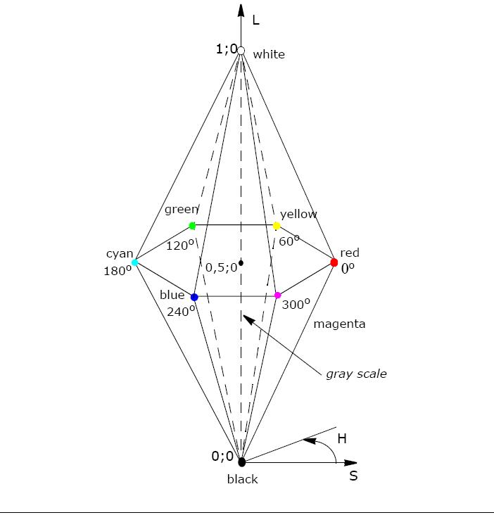
Intensity component - lightness (HLS) or value (HSV), indicates the illumination level. Both vary from 0 (black, no light) to 1 (white, full illumination). The difference between the two is that maximum saturation of hue (S=1) is at value V=1 (full illumination) in the HSV color model, and at lightness L=0.5 in the HLS color model.
The HSV color space is essentially a cylinder, but usually it is represented as a cone or hexagonal cone (hexcone) as shown in the Figure “HSV Solid”, because the hexcone defines the subset of the HSV space with valid RGB values. The value V is the vertical axis, and the vertex V=0 corresponds to black color. Similarly, a color solid, or 3D-representation, of the HLS model is a double hexcone (Figure “HSV Solid”) with lightness as the axis, and the vertex of the second hexcone corresponding to white.
Both color models have intensity component decoupled from the color information. The HSV color space yields a greater dynamic range of saturation. Conversions from and vice versa in oneIPL are performed in accordance with the respective pseudocode algorithms [Rogers85] given in the descriptions of corresponding conversion functions.
CIE XYZ Color Model
The XYZ color space is an international standard developed by the CIE (Commission Internationale de l’Eclairage). This model is based on three hypothetical primaries, XYZ, and all visible colors can be represented by using only positive values of X, Y, and Z. The CIE XYZ primaries are hypothetical because they do not correspond to any real light wavelengths. The Y primary is intentionally defined to match closely to luminance, while X and Z primaries give color information. The main advantage of the CIE XYZ space (and any color space based on it) is that this space is completely device-independent. The chromaticity diagram in Figure “CIE xyY Chromaticity Diagram and Color Gamut” is in fact a two-dimensional projection of the CIE XYZ sub-space. Note that arbitrarily combining X, Y, and Z values within nominal ranges can easily lead to a “color” outside of the visible color spectrum.
The position of the block of RGB-representable colors in the XYZ space is shown in Figure “RGB Colors Cube in the XYZ Color Space”.
oneIPL functions use the following basic equations [Rogers85], to convert between gamma-corrected R’G’B’ and CIE XYZ models:
X = 0.412453*R' + 0.35758 *G' + 0.180423*B'
Y = 0.212671*R' + 0.71516 *G' + 0.072169*B'
Z = 0.019334*R' + 0.119193*G' + 0.950227*B'
The equations for X,Y,Z calculation are given on the assumption that R’,G’, and B’ values are normalized to the range [0..1].
oneIPL functions use the following basic equations [Rogers85], to convert between gamma-corrected R’G’B’ and CIE XYZ models:
R' = 3.240479 * X - 1.53715 * Y - 0.498535 * Z
X = 0.412453*R' + 0.35758 *G' + 0.180423*B'
G' = -0.969256 * X + 1.875991 * Y + 0.041556 * Z
Y = 0.212671*R' + 0.71516 *G' + 0.072169*B'
B' = 0.055648 * X - 0.204043 * Y + 1.057311 * Z
Z = 0.019334*R' + 0.119193*G' + 0.950227*B'
The equations for R’,G’, and B’ calculation are given on the assumption that X,Y, and Z values are in the range [0..1].
CIE LUV and CIE Lab Color Models
The CIE LUV and CIE Lab color models are considered to be
perceptually uniform and are referred to as uniform color models.
Both are uniform derivations from the standard CIE XYZ space.
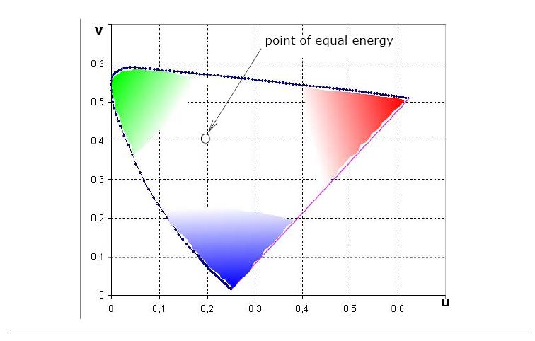
“Perceptually uniform” means that two colors that are equally distant
in the color space are equally distant perceptually. To accomplish
this approach, a uniform chromaticity scale (UCS) diagram was
proposed by CIE (Figure “CIE u’, v’ Uniform Chromaticity
Scale Diagram”). The UCS diagram uses a mathematical
formula to transform the XYZ values or x, y coordinates (Figure “CIE xyY
Chromaticity Diagram and Color Gamut”),
to a new set of values that present a visually more accurate
two-dimensional model. The Y lightness scale is replaced with a new
scale called L that is approximately uniformly spaced but is more
indicative of the actual visual differences. Chrominance components
are U and V for CIE LUV, and a and b (referred to also
respectively as red/blue and yellow/blue chrominances) in CIE Lab.
Both color spaces are derived from the CIE XYZ color space.
The CIE LUV color space is derived from CIE XYZ as follows ([Rogers85]),
B' = 0.055648 * X - 0.204043 * Y + 1.057311 * Z
L = 116. * (Y/Yn)1/3. - 16.
The equations for R’,G’, and B’ calculation are given on the assumption that X,Y, and Z values are in the range [0..1].
U = 13. * L * (u - un)
CIE LUV and CIE Lab Color Models
V = 13. * L * (v - vn)
where
u = 4.*X / (X + 15.*Y + 3.*Z)
v = 9.*Y / (X + 15.*Y + 3.*Z)
un = 4.*xn / ( -2.*xn + 12.*yn + 3. )
vn = 9.*yn / ( -2.*xn + 12.*yn + 3. )
Inverse conversion is performed in accordance with equations:
Y = Yn * ((L + 16.) / 116.)3.
X = -9.* Y * u / ((u - 4.)* v - u * v )
Z = (9.* Y - 15*v*Y - v*X) / 3. * v
where
u = U / (13.* L) + un
v = V / (13.* L) + vn
and un, vn are defined above.
Here xn = 0.312713, yn = 0.329016 are the CIE chromaticity
coordinates of the D65 white point
([ITU709]),
and Yn = 1.0 is the luminance of the D65 white point. The values
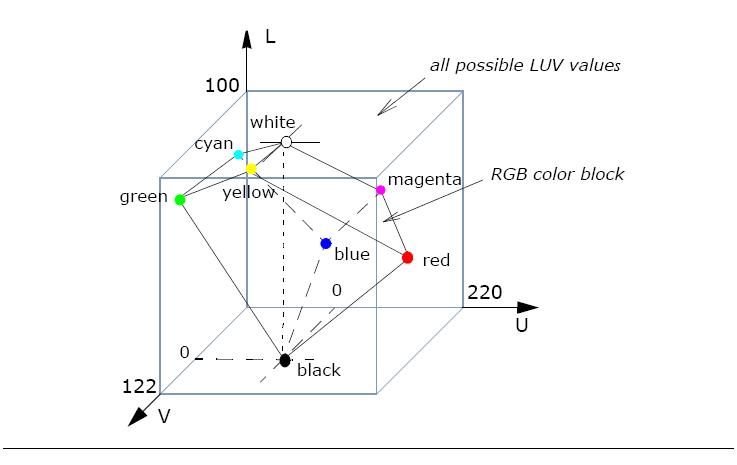
of the L component are in the range [0..100], U component in the
range [-134..220], and V component in the range [-140..122].
The RGB-representable colors occupy only part of the LUV color space (see Figure 6-12) limited by the nominal ranges, therefore there are many LUV combinations that result in invalid RGB values.
The CIE Lab color space is derived from CIE XYZ as follows:
v = V / (13.* L) + vn
L = 116. * (Y/Yn)1/3. - 16 for Y/Yn > 0.008856
L = 903.3 * (Y/Yn)1/3. for Y/Yn⩽ 0.008856
a = 500. * [f(X/Xn)-f(Y/Yn)]
b = 200. * [f(Y/Yn)-f(Z/Zn)]
where
f(t) = t1/3. - 16 for t > 0.008856
f(t) = 7.787*t + 16/116 for t ⩽ 0.008856
Here Yn = 1.0 is the luminance, and Xn = 0.950455, Zn =
1.088753 are the chrominances for the D65 white point.
The values of the L component are in the range [0..100], a and
b component values are in the range [-128..127].
Inverse conversion is performed in accordance with equations:
Y = Yn * P3.
X = Xn * (P + a/500.)3.
Z = Zn * (P - b/200.)3.
where
P = (L +16)/116.