CIE Chromaticity Diagram and Color Gamut#
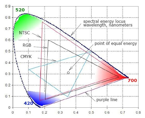
Figure CIE (Commission Internationale de l’Eclairage) xyY
Chromaticity Diagram and Color Gamut
presents a diagram of all visible colors. It is called a chromaticity
diagram and was developed as a result of the experimental investigations
performed by CIE (International Commission on Illumination,
http://members.eunet.at/cie). The diagram presents visible colors as a
function of x (red) and y (green) components called chromaticity
coordinates. Positions of various spectrum colors (from violet to red)
are indicated as the points of a tongue-shaped curve called spectrum
locus. The straight line connecting the ends of the curve is called the
purple line. The point of equal energy represents the CIE standard for
white light. Any point within the diagram represents some mixture of
spectrum colors. The pure or fully saturated colors lie on the spectrum
locus. A straight-line segment joining any two points in the diagram
defines all color variations that can be obtained by additively
combining these two colors. A triangle with vertices at any three points
determines the gamut of colors that can be obtained by combining
corresponding three colors.
The structure of the human eye that distinguishes three different stimuli, establishes the three-dimensional nature of color. The color may be described with a set of three parameters called tristimulus values, or components. These values may, for example, be dominant wavelength, purity, and luminance, or so-called primary colors: red, green, and blue.
The chromaticity diagram exhibits that the gamut of any three fixed
colors cannot enclose all visible colors. For example, Figure CIE
xyY Chromaticity Diagram and Color Gamut shows schematically the
gamut of reproducible colors for the RGB primaries of a typical color
CRT monitor, CMYK color printing, and for the NTSC television.
CIE xyY Chromaticity Diagram and Color Gamut#